FREED0M-4 Background
After SANDST0RM-1 monosynth, I had an idea to build a new polyphonic synth with stereo sound.
To simplify the design, I decided to remove all computer-controlled parameters, so patch/preset support was dropped.
Building a polysynth is painful, because it each voice is its own synth itself. Only a few things are not duplicated per voice.
The name was inspired by the war in Ukraine. I also wanted to use blue-yellow colors for the hardware.
Features
-
Analog signal path
- 4 voices:
- VCO: triangle/pulse/saw, pulse PWM
- 5 octaves
- 3 octave offsets
- Auto-tuning
- Suboctave oscillator
- MIDI input
- Velocity support
- Pitch-wheel support
- Aftertouch support
- Modwheel support
- VCF:
- 24dB Low-pass filter
- Self-oscillating
- Key follow
- Bass boost compensation on lower frequencies
-
Noise generator
- 2 x envelopes:
- VCA envelope (ADSR), modulates VCO / VCA
- VCF envelope (ADSR), modulates VCF
- 3 x LFOs:
- LFO1 analog: triangle/pulse/saw, PWM
-
Modulates VCO / VCF
- LFO2 digital: triangle/pulse/saw/random/noise/…
-
Modulates VCO PWM
- LFO3 digital: triangle/pulse/saw/random/noise/…
- Modulates VCO / VCF / VCA / panning
- Stereo panning
- stereo panning effects per voice
- Various stereo modes
- Power:
- 24V DC (ca. 300mA?), ca. 7W
- Internal voltages: +15V, -15V, +5V, -5V (, +3.3V)
Voice boards
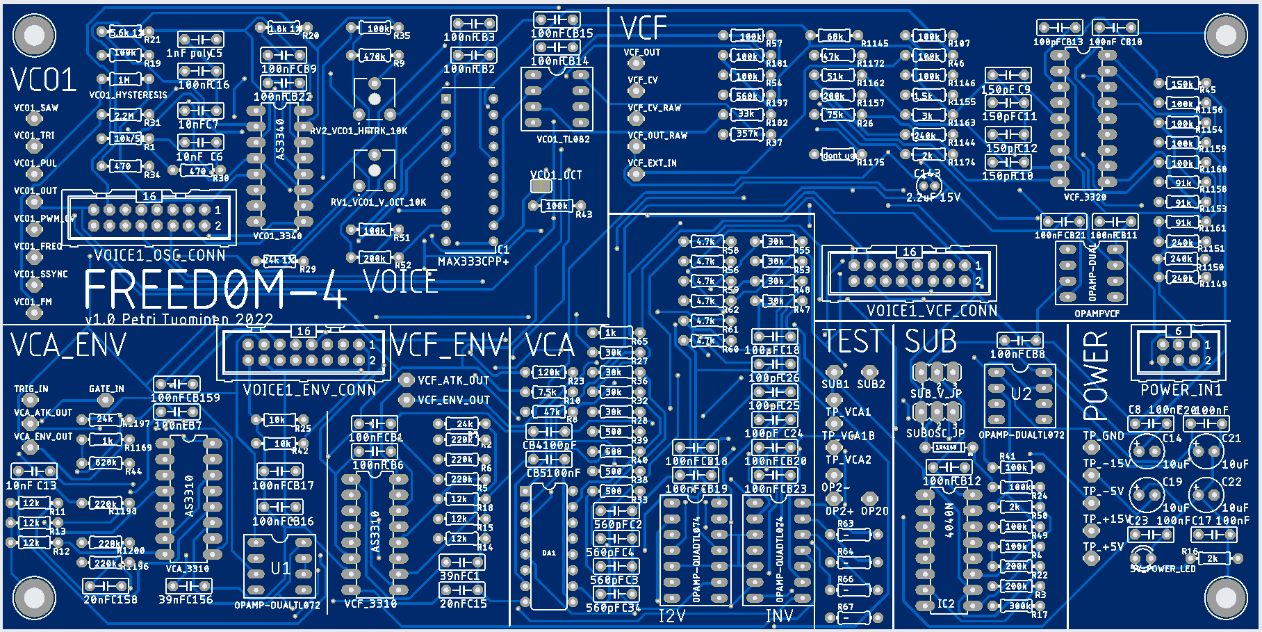
There are 4 identical voice boards.
VCO Oscillator is based on CEM3340 from 1980 (clone by Alfa AS3340).
There are two ADSR envelopes (for VCA and VCF) CEM3310 from 1980 (clone by Alfa AS3310)
-Filter is CEM3320 from 1980 (clone by Alfa AS3320)
The voices are somewhat based on Sequential Pro-1 design.
VCF filter Bass boost is also similar to Prophet5/Pro-1
Suboscillator is based on 4040 binary counter. It counts oscillator’s pulse waves and counters binary values (suboctaves) are then summed together.
VCA is SSM2164 voltage controlled amplifier from ca. 1980. (Coolaudio V2164 clone is used).
MAX333 chip is used to switch on/off waveforms that are combined together into VCO output.
Controls board
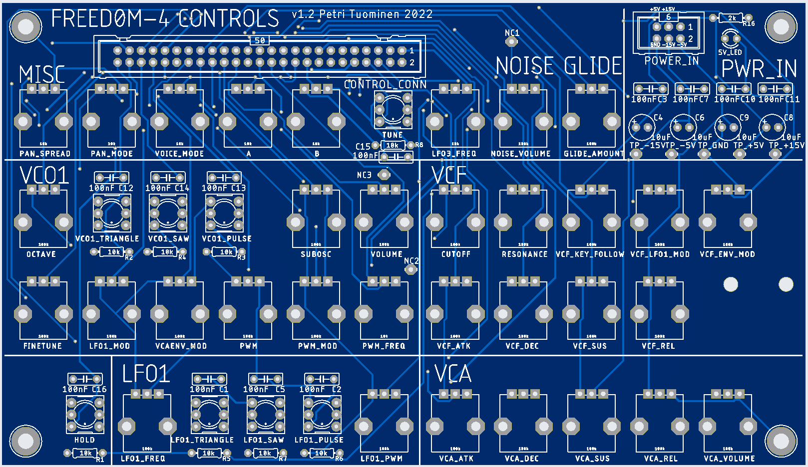
This is a simple board for all the user controls and sending them to the Main board and Analog Input board.
Pots connected to the CPU (Arduino) use 10k values, others use 100k to minimise power draw.
CPU board

The CPU board contains Arduino NANO (2k RAM, 1x EEPROM) as the main processor. The main idea was to keep this as a hardware project, not a software project. So I like to use a minimal CPU for this.
CPU also contains several IO chips to generate various control signals for the synth:
- LTC1660 8x 10bit DAC (via SPI)
- TLC5628 8x 8bit DAC (via SPI)
- MCP23S17 16x IO (via SPI)
Main outputs:
- 4x gate CVs
- 4x voice frequencies
- 4x voice left + right volumes
- LFO2, LFO3
- pitchwheel CV
- modwheel mod
- LEDs
Inputs:
- MIDI in (thru 6N137 optocoupler to Arduino Serial port), which is used to receive the notes.
- Controls (Octave selector, voice mode, pan params, tuning, hold, LFO3 params, LFO2 params)
- 4x voice pulse oscillators
- 2x test buttons, 1x test pot
CPU is also connected to MIDI input interface (thru 6N137 optocoupler to Arduino Nano serial port),
Analog inputs board
Picture of old v1.1 PCB with various problems.
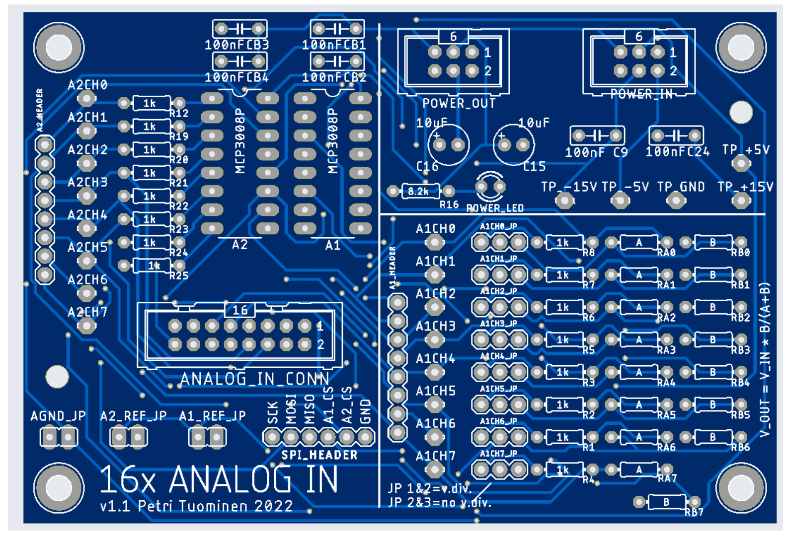
This is a generic board that expands Arduino with 16 analog inputs. Analog inputs are used to read control pots and use them with CPU board.
Design is built around two MCP3008 8xADC ICs, which the CPU access via SPI bus.
Board also contains optional voltage dividers (resistor “B”s) for attenuating input voltages.
LFO board
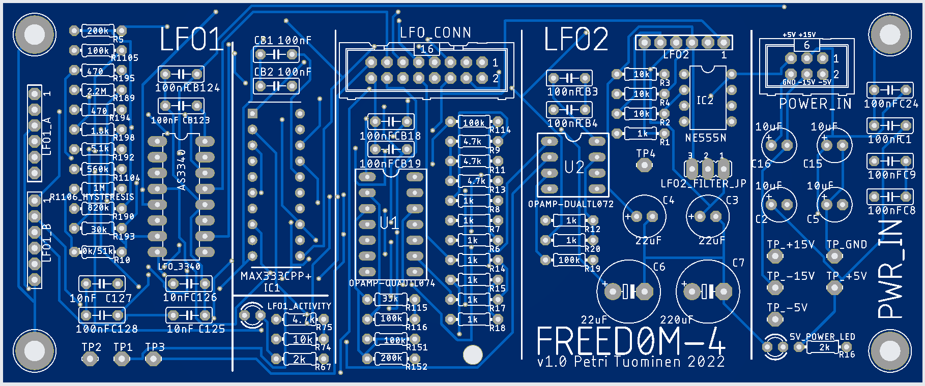
LFO board contains two analog LFO circuits.
LFO1 board uses CEM3340 Oscillator chip, the same chip used with VCO. LFO1 waveforms are mixed together with MAX333.
LFO1 can be used to modulate VCO frequency and/or VCF cutoff CV.
LFO1 has LED to indicate LFO pulsing, but it doesn’t work very well.
LFO2 uses 555 timer with capacitors to generate triangle-like waveform. LFO2 was planned to be used to modulate VCO PWM. However, the waveform and frequency wasn’t very nice, and large capacitors also caused ripple with +5V supply. So LFO2 was disconnected, and changed to digital CPU-based LFO.
Main board

Main board joins all boards together. It also generate the following CVs:
-
Summing opamp to generate “global” (same for every voice) VCO modulation signal, combining Pitchwheel, VCO LFO3 mod, VCO LFO1 mod, finetune and octave
-
Summing opamp to generate “global” VCF CV, combining Cutoff, MIDI control (modwheel/aftertouch), VCF LFO1 mod and VCF LFO3 mod
-
Summing opamp to generate “global” VCF external audio input, combining Noise, Ext audio in and Ext2 audio in
Mixer board
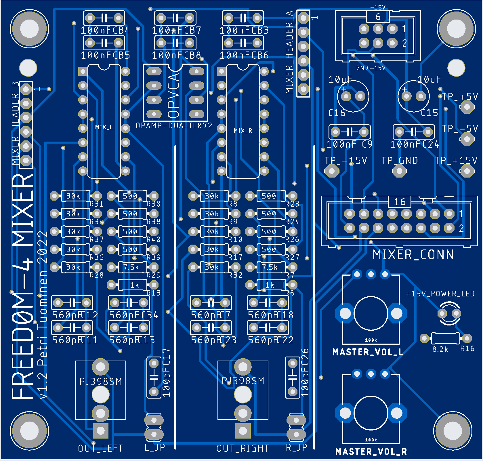
Design uses two SSM2164 4xVCA ICs, each for LEFT and RIGHT channel, making this 4+4 channel audio mixer.
All 4 voice audio signals are sent as inputs to both LEFT and RIGHT mixers.
8 Control voltages (loudness) are generated by the CPU separately for each voice per LEFT/RIGHT channel. Thus each channel can be panned freely in the stereo field.
There seems to be some audible “pops” when VCA value is changed by large amounts. Possibly a capacitor might fix it.
Noise board

Noise board is based on generic transistor noise amplifier.
Noise volume potentiometer (located in Control board) attenuates the noise by grounding the output. This allows volume control using just a single pin.
VCA board
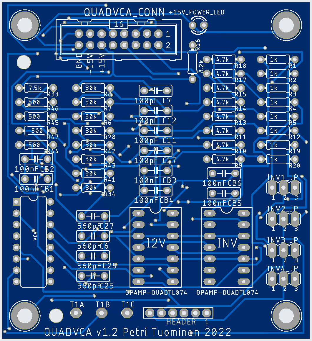
Generic board containing 4 VCAs.
VCA is a SSM2164 voltage controlled amplifier from ca. 1980. (Coolaudio V2164 clone is used).
SSM2164 has a –33 mV/dB gain constant, so VCA control voltages work as follows:
- -100dB at +3.3V
- 0dB at 0V
- +20dB at -0.66V
This board was planned to be used to modulate various signals with LFO, but these were handled in Controls board v2.1 instead.
Currently Quad-VCA is used to generate voice-specific key follow signals, but these should be replaced with 4-gang potentiometer, thus making the board unnecessary.
Power board

Input voltage is +24V DC.
Power board provides +5V, +15V, -5V and -15V DC voltages via common 6-pin connectors.
Design is based on Mornsun DC-DC power modules: A24S05S-2WR2 (+5V and -5V at 2W) A24S15S-2WR2 (+15V and -15V at 2W)
However, synth’s +-15V power usage was too high, so it was replaced with this DC-DC buck converter: https://www.ebay.com/itm/264734859946?var=564895999202
This required heavy patching of the board.
Power board contains 1N4004 diode polarity protection and a fuse (“1A Ceramic AXIAL LEAD Fast Blow Fuse F1A 1 Amp”).
Power usage is around 350mA at 24V (8.4W).
Version 1
I spent basically the entire summer 2022 by building and fixing this.
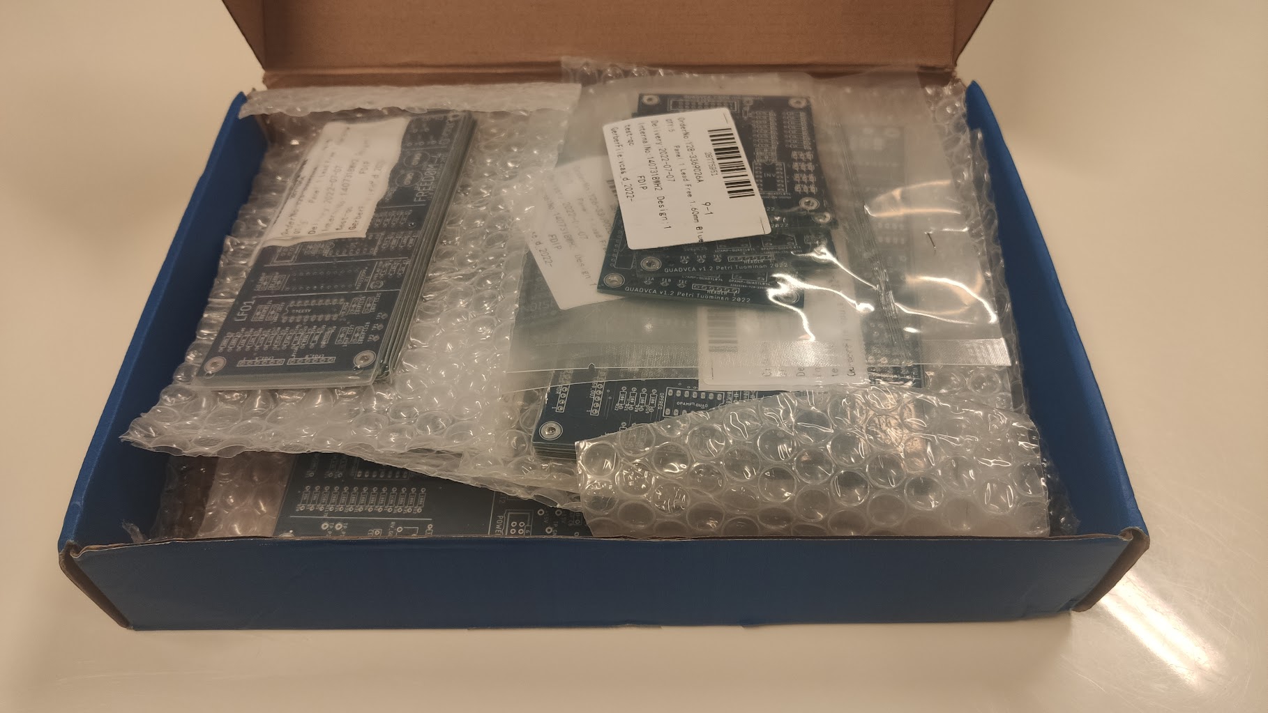
Box full of PCBs
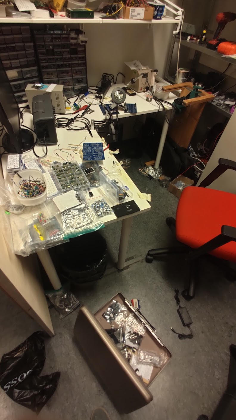
Building at nights in the office
Testing the voice card
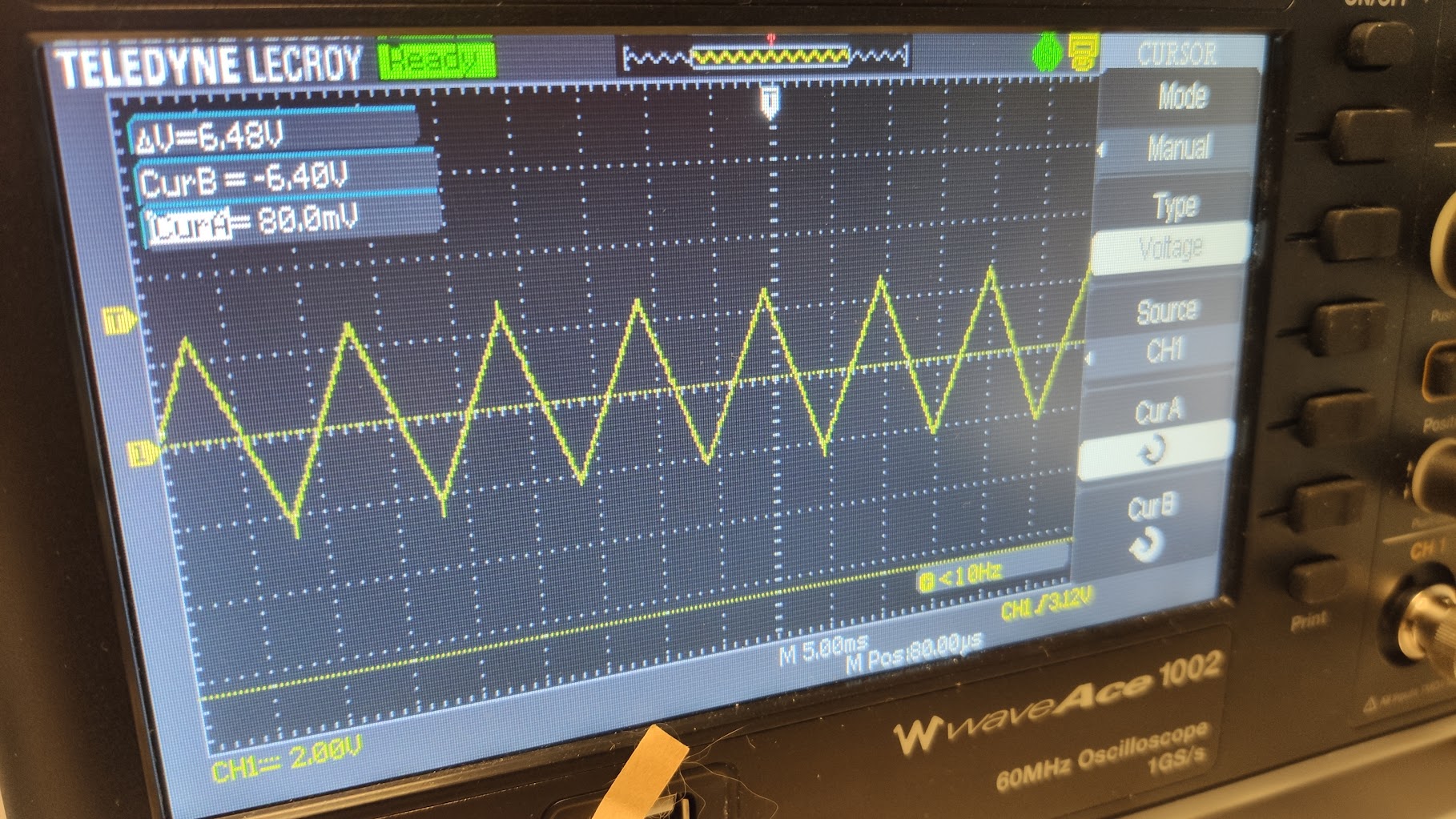
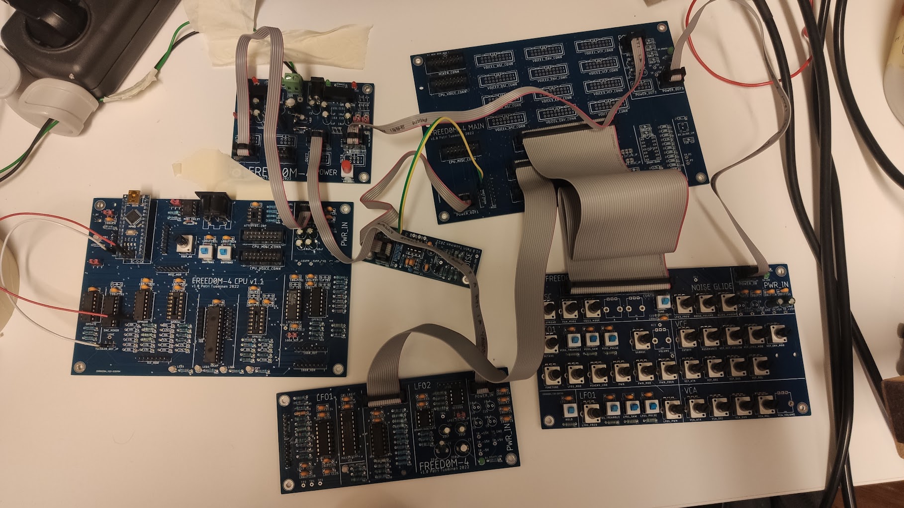
Building and testing
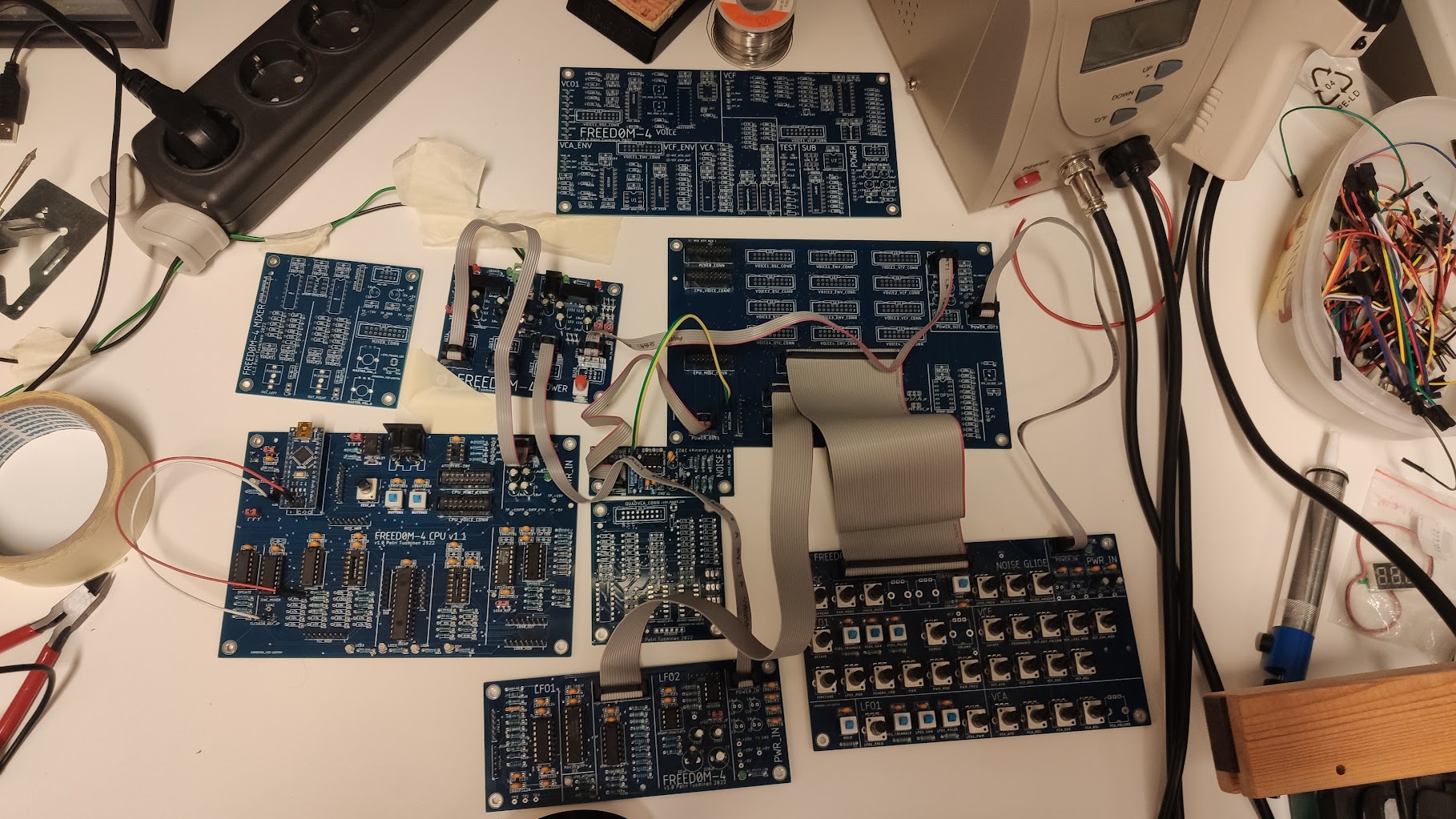
More PCBs
Attempting to package everything into old cash register that I found from a trashcan
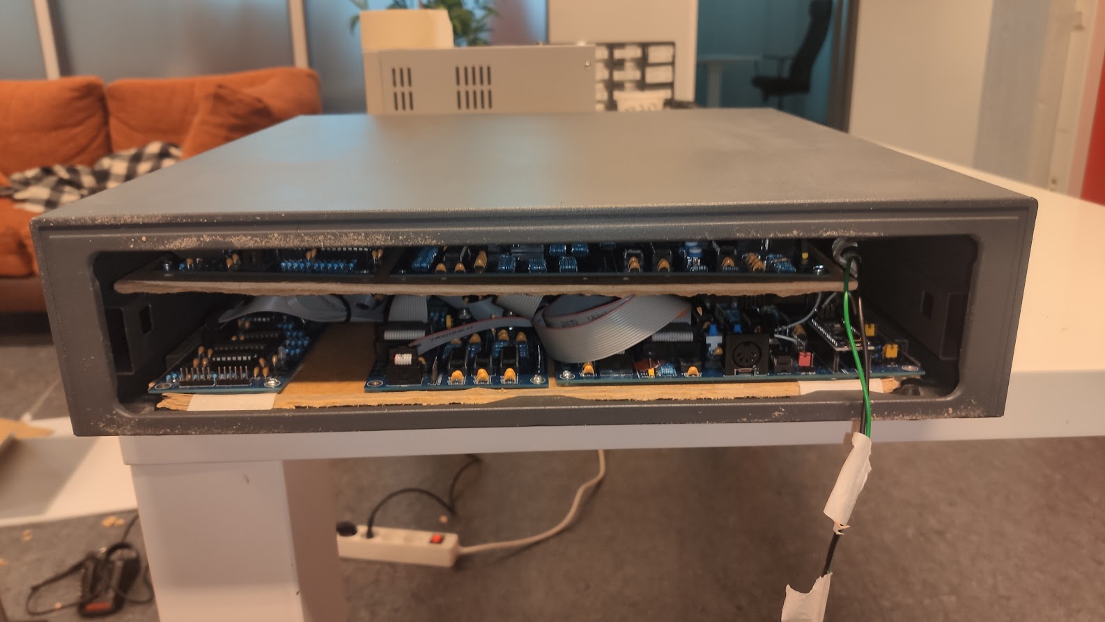
Two layers of PCBs stacked
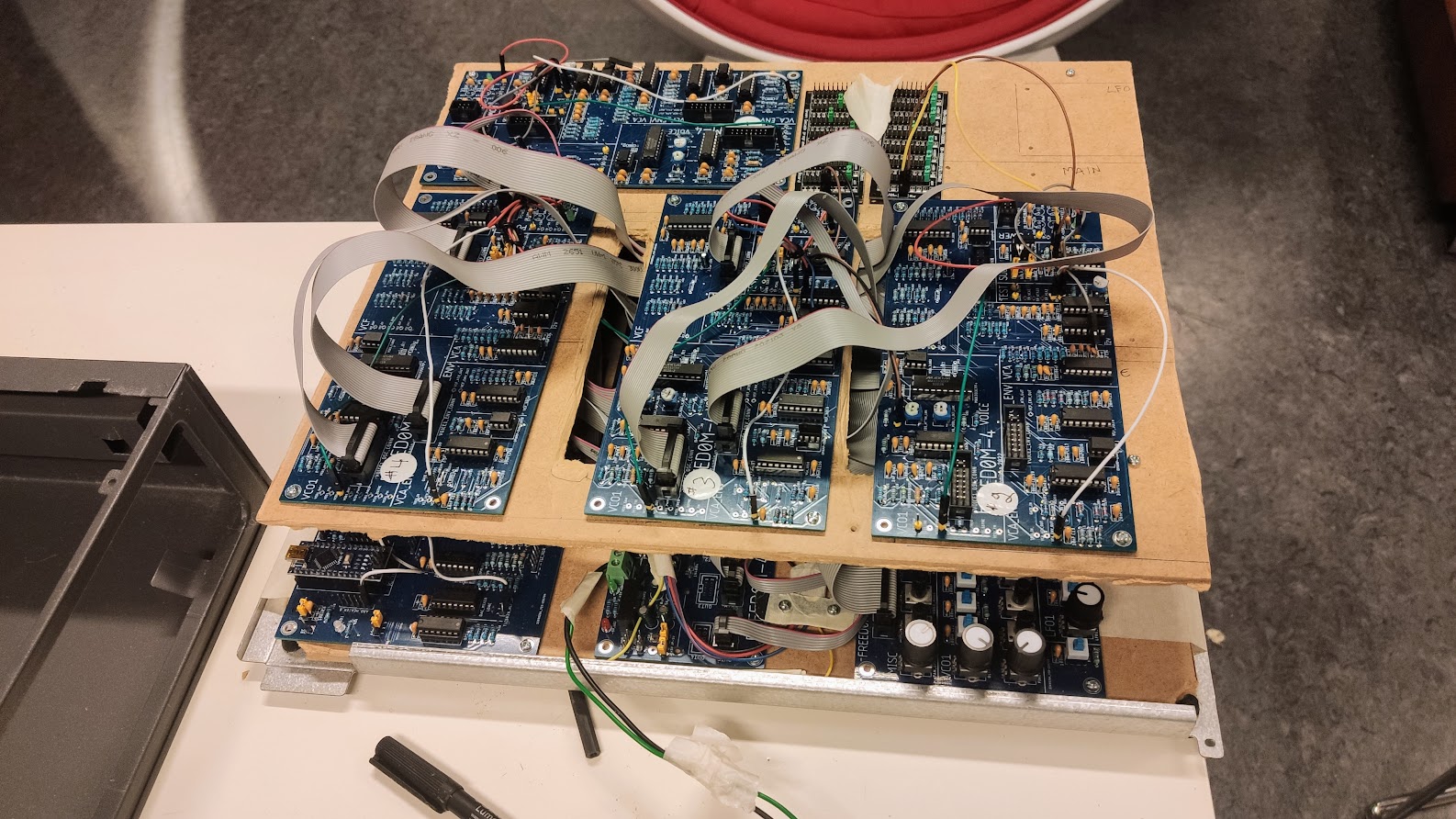
It is getting hard to manage all the cables and boards
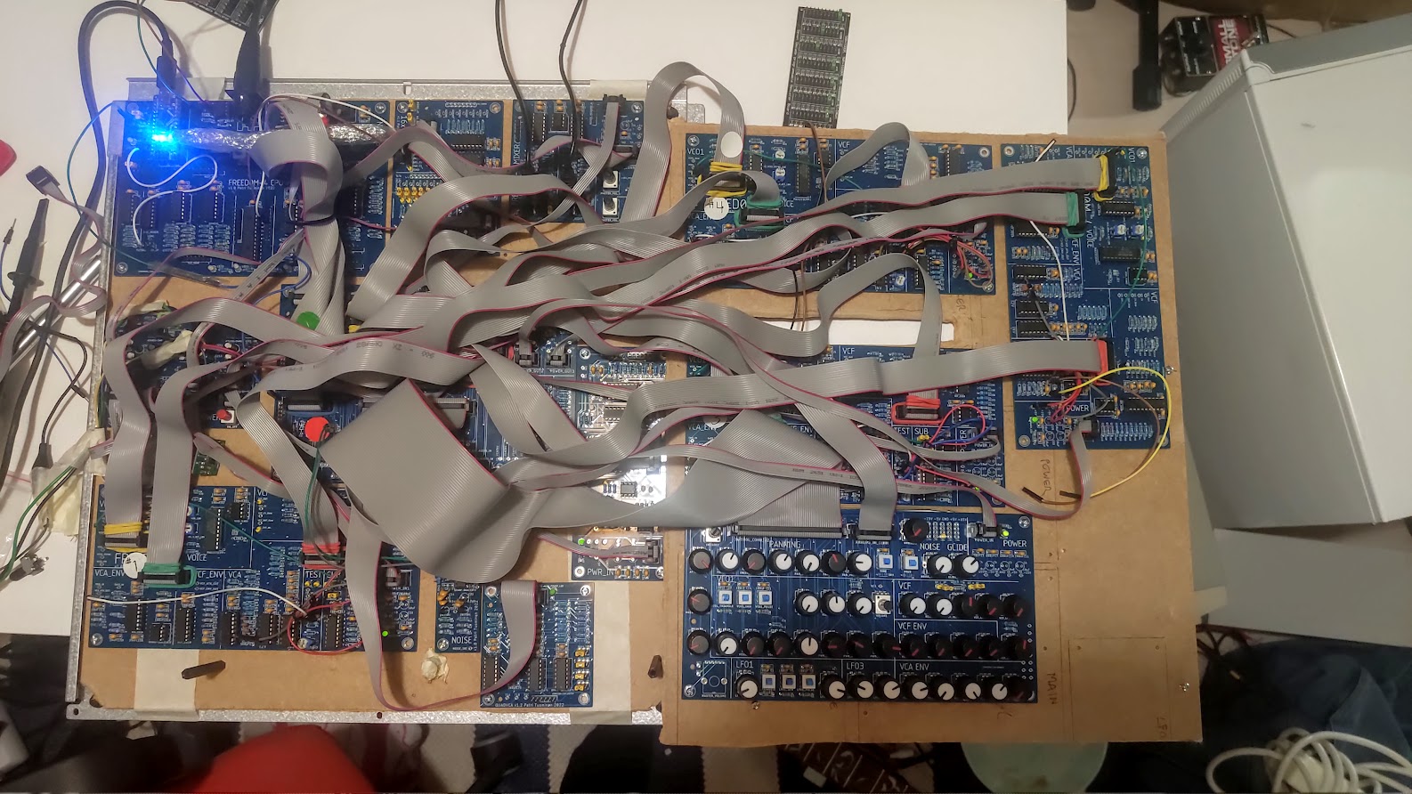
…the story continues…